



ETFE Small Solar Panel Hot Spot Failure: The Risk of Improper Silicone Application
Small solar panels are widely used in IoT devices, GPS trackers, remote monitoring equipment, smart sensors, outdoor electronics and other compact electronic products. Because these modules are often installed directly onto a plastic housing, enclosure or electronic device, the way the solar panel is fixed and sealed can have a significant impact on long-term reliability.
The following real-world failure case shows an important issue that is sometimes overlooked: improper application of silicone or other opaque materials on the active surface of a small solar panel can create local shading, electrical mismatch and potentially severe hot-spot damage.
1. A Real Small Solar Panel Failure Case
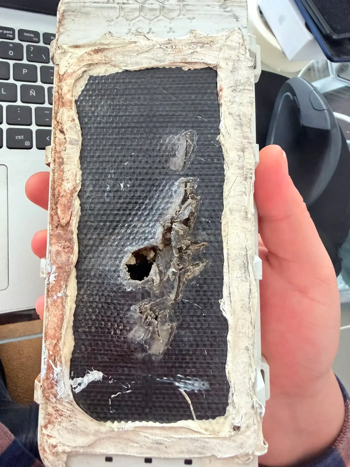
The photos below show a small ETFE solar panel integrated into an electronic device. A large amount of silicone-like material has been applied around and over the solar panel surface. The solar cell also shows a severely damaged area, including localized burning and a visible burn-through hole.
This type of damage is consistent with a serious localized thermal failure. When part of a solar cell is continuously shaded while the remaining cells are illuminated, the electrical operating condition of the cell string can become highly unbalanced. Under certain conditions, the shaded cell may be forced into reverse bias, generating localized heat.
This phenomenon is commonly referred to as a hot spot.
2. How Can Silicone Cause a Solar Panel Hot Spot?
Silicone itself is not necessarily harmful to a solar panel. In fact, silicone materials can be useful for mechanical fixation, sealing and environmental protection when they are correctly selected and applied.
The problem occurs when silicone or another opaque material unintentionally covers part of the active photovoltaic area.
For example, if a portion of a solar cell is covered by a thick layer of opaque silicone, that area receives significantly less sunlight than the uncovered portion of the same cell. The shaded area therefore generates less photocurrent.
If the affected cell is electrically connected in a series string, the shaded cell can become a limiting point within the circuit. Depending on the electrical configuration, illumination level, bypass protection and severity of the shading, the cell may experience reverse bias and localized heating.
The result can be:
- Localized temperature increase
- Cell discoloration
- Encapsulant degradation
- Localized carbonization or burning
- Cell cracking or electrical damage
- Permanent power loss
- In severe cases, burn-through of the solar cell or encapsulation
3. Why Small Solar Panels Are Especially Sensitive
Small solar panels used in IoT and electronic devices are often very different from conventional large rooftop modules.
A conventional framed solar module normally has a relatively open installation environment, defined mounting points and a controlled mechanical structure. A small embedded solar module, however, may be installed directly into a plastic housing or molded product.
This creates several additional engineering risks:
- Limited installation area
Small modules have very limited active photovoltaic area. Even a small amount of shading can represent a significant percentage of the total active area. - Direct integration with the device housing
The solar panel may be bonded directly to a plastic enclosure, which can make sealing and mechanical fixation more complicated. - Silicone or adhesive may spread onto the active area
During assembly, excessive adhesive can flow onto the front surface of the solar panel. If the material is opaque or significantly reduces light transmission, it can create local shading. - The solar panel may operate continuously outdoors
Outdoor equipment can experience strong sunlight and elevated temperatures. A small localized hot spot can therefore become much more severe under high irradiance and high ambient temperature conditions.
4. Typical Installation Mistakes
The following installation practices should be avoided when integrating small ETFE solar panels into electronic equipment.
| Installation Problem | Potential Risk |
|---|---|
| Silicone covering the active cell area | Partial shading and local current mismatch |
| Thick opaque adhesive directly over the cell | Reduced light transmission and localized heating |
| Adhesive flowing onto the front surface | Uncontrolled shading area |
| Uneven pressure on the solar panel | Cell cracking or mechanical stress |
| Improper bending or installation | Microcracks and electrical degradation |
| Insufficient thermal consideration | Higher operating temperature and accelerated aging |
| Sealing without considering the active area | Reduced power output and reliability problems |
5. Silicone Should Be Used Around the Solar Panel — Not Randomly Across the Active Area
For compact solar applications, the recommended approach is to clearly define the bonding, sealing and active photovoltaic areas during the mechanical design stage.
The adhesive or silicone should normally be positioned in designated non-active areas whenever possible.
The front photovoltaic surface should remain unobstructed unless the material has been specifically evaluated for optical transmission and long-term outdoor use.
This is especially important for custom small solar panels because the position of cells, busbars, soldering areas, cables and active photovoltaic regions can vary according to the customer's mechanical design.
6. Hot Spot Risk Is Not Simply a "Solar Panel Quality" Problem
When a small solar panel shows a localized burn mark, it is tempting to assume that the solar cell itself was defective.
However, hot-spot damage can result from the interaction between the solar module and the installation environment.
Possible contributing factors include:
- Partial shading
- Improper adhesive application
- Cell cracks or microcracks
- Interconnection problems
- Electrical mismatch
- Incorrect module configuration
- Improper installation pressure
- High operating temperature
- Improper mechanical integration
Therefore, the solar panel should be considered as part of the complete device design rather than as an isolated component.
7. How to Properly Integrate a Small ETFE Solar Panel
For IoT devices and compact outdoor electronics, the mechanical and electrical design of the solar panel should be considered together.
Recommended Design Process
- Define the available installation area.
- Identify the actual active photovoltaic area.
- Define the required voltage and power output.
- Determine the bonding and sealing method.
- Keep opaque adhesives away from active cell areas.
- Consider the thermal environment of the complete device.
- Check cable routing and soldering areas.
- Evaluate partial shading conditions.
- Test the assembled device under realistic outdoor conditions.
8. Why ETFE Is Commonly Used for Small Solar Panels
ETFE is widely used as a front protection material for lightweight and compact solar modules. It can provide a good combination of low weight, flexibility, transparency and outdoor durability.
For small electronic products, ETFE construction can be particularly useful where a rigid glass module would be too heavy, too thick or mechanically unsuitable.
However, the use of ETFE does not eliminate installation risks. The complete module structure, cell layout, adhesive system and mechanical installation must still be designed correctly.
9. Custom Solar Panel Design Should Include the Installation Method
A common mistake in solar product development is to specify only the electrical parameters, such as voltage, current and power.
For small solar panels, the mechanical installation method can be equally important.
When requesting a custom solar panel, customers should provide:
- Maximum available dimensions
- Required voltage and power
- Required cell technology
- Front encapsulation requirements
- Mounting or bonding method
- Housing or enclosure design
- Expected outdoor environment
- Temperature conditions
- Required cable and connector position
- Any areas that must remain free of adhesive
This information allows the solar panel manufacturer to consider the electrical, optical, thermal and mechanical requirements together.
10. For Leaves Custom Small Solar Panel Engineering
For Leaves Limited manufactures customized small solar panels for IoT devices, sensors, monitoring equipment, outdoor electronics, smart lighting and other compact applications. View our standard product: SOLAR PANEL FOR IOT DEVICES
Our custom solar modules can be designed according to the customer's available installation space, electrical requirements and mechanical integration requirements.
Depending on the application, we can provide different module constructions including ETFE, PET, PCB-backed and other customized structures.
For compact products, the solar panel should not simply be treated as a flat power source. The cell layout, encapsulation, cable position, bonding area and installation method should all be considered during the design process.
11. Conclusion
A small solar panel can be electrically correct and still fail if it is improperly integrated into the final device.
The case shown above is a useful reminder that excessive silicone or other opaque materials on the active photovoltaic area can create partial shading. Under suitable electrical and environmental conditions, localized heating and hot-spot damage can occur.
For small ETFE solar panels used in IoT and outdoor electronic products, proper mechanical integration is therefore just as important as selecting the correct voltage and power.
Design the solar panel together with the device — not separately from it.
Small Solar Panel Design Checklist
| Item | What to Check |
|---|---|
| Panel size | Maximum available space |
| Vmp | Required operating voltage |
| Voc | Maximum allowable voltage |
| Power | Required energy generation |
| Cell technology | Mono / IBC / other |
| Front material | ETFE / PET / other |
| Adhesive area | Keep active area unobstructed |
| Cable position | Define before production |
| Operating temperature | Indoor / outdoor |
| Shading | Check surrounding structures |
| Mounting | Adhesive / screw / molding / housing integration |
| Waterproofing | Define sealing method |
| Thermal conditions | Consider enclosure temperature |
FORLEAVES provides full mechanical & electrical customized PV modules with professional structural design to avoid hot spot risks caused by improper adhesive installation. Submit your device drawings and requirements for detailed technical review and quotation:
Tags:ETFE solar panel,small solar module,IoT solar power,hot spot failure,silicone sealing risk,custom mini solar panel,embedded solar for monitoring equipment
